- #Teensy driver 2.0 install
- #Teensy driver 2.0 driver
- #Teensy driver 2.0 Patch
- #Teensy driver 2.0 Activator
- #Teensy driver 2.0 Pc
Note: This does not come with a USB cable.
#Teensy driver 2.0 install
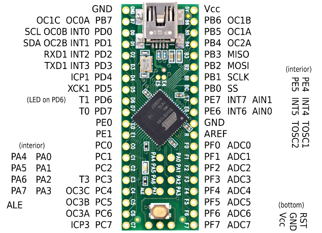
The Teensy++ comes pre-flashed with a bootloader so you can program it using the on-board USB connection: No external programmer needed! You can program the Teensy in your favorite IDE using C *or *you can install the Teensyduino add-on for the Arduino IDE and write Arduino sketches for Teensy! The Teensy++ breaks out all of the IO available on the AT90USB1286 to breadboard-friendly 0.1 inch spaced headers so you can hook up a load of peripherals.
#Teensy driver 2.0 driver
After installing the Driver Connect the Teensy via USB to the computer and wait till the computer recognize it (It may take some time in the first time). The Teensy is a breadboard-friendly development board with loads of features in a, well, teensy package. Run the Program as Administrator, Go to settings as in Photo01, and start by installing Python first and wait till you finish, then install pySerial, and finally install Teensy++2.0 Driver.

Raspberry Pi Sound Cards and Audio Accessories.Raspberry Pi Shield and Industrial Products.You can now browse games using the D-Pad and select a game to play using the A or B button. The RGB LEDs will flash red during uploading and briefly flashes green after the upload is completed. Click on the Upload flash image button to start uploading the to the flash chip.' button at the right of the Upload flash image button, browse to the extracted folder and select the flash-image file.
#Teensy driver 2.0 Patch
From the Options menu check the apply SSD1309 display patch option.
#Teensy driver 2.0 Activator
To upload the original game library to the flashchip, download the Portable Activator package, unzip it and double click the run-uploader-gui-windows batch file to start the tool. The difference in displays is only in the display initialisation and original games can be patched on the fly using my Python tools so it's possible to play original Arduboy games. The almost is because I chose to use a larger 1.54" SSD1309 display over those small 0.96" SSD1306. The Arduboy GT is almost fully compatible with an original Arduboy.

#Teensy driver 2.0 Pc
If reset is pressed your PC should also make a USB connect sound. If everything is well you should see a USB boot icon on the display. The header pin holes surrounded by white outline should remain clear. Make sure you insert the display in the left most header pin holes. This will make sure the pins will fit into the custom PCB holes far enough.Īlso try inserting the OLED display and tilt it a little so the pins make contant and then power the Arduboy GT from USB PC connection. the pins on the module must be heated with a soldering iron and pushed down a bit. do not use excessive force.īefore the OLED display can be soldered. The easiest way to do this is to put the Teensy with the pinheaders on the workbench and use a thin flat screw driver or other flat tool to gently push the black strips down at the sides little by little until they come off. After soldering the pins at the top, remove the Teensy from the custom PCB and remove the black strips of the pinheaders. Now the pins can be soldered at the top of the teensy. After that turn the teensy and custom PCB around and put it on your workbench. I believe 2.0 will meet all of my requirements but I do use a Teensy 4.1. Do this by keeping the Teensy upside down and put the custom PCB on top. PiratePointBrewer May 11, 2021, 3:26pm 1.

There is no driver for it, probably the only way is to use external jtag adapter. After all pins are seated put the teensy in the custom PCB. The main chip AT90USB1286 user guide doesnt give any clear indication of what driver to use with the USB and I didnt see any references in the openocd guide. Don't forget to insert the two pins in the middle. the easiest way to solder these on straight is to put the Teensy upside down and insert header pins. Prepping the Teensy - soldering pin headersįirst the pin headers must be soldered to the Teensy.

Before the Teensy can be soldered to the custom PCB, some preperations need to be made. This offers best compatibility with Arduboy. Because it has all the GPIO pins broken out that are used by official Arduboy.


 0 kommentar(er)
